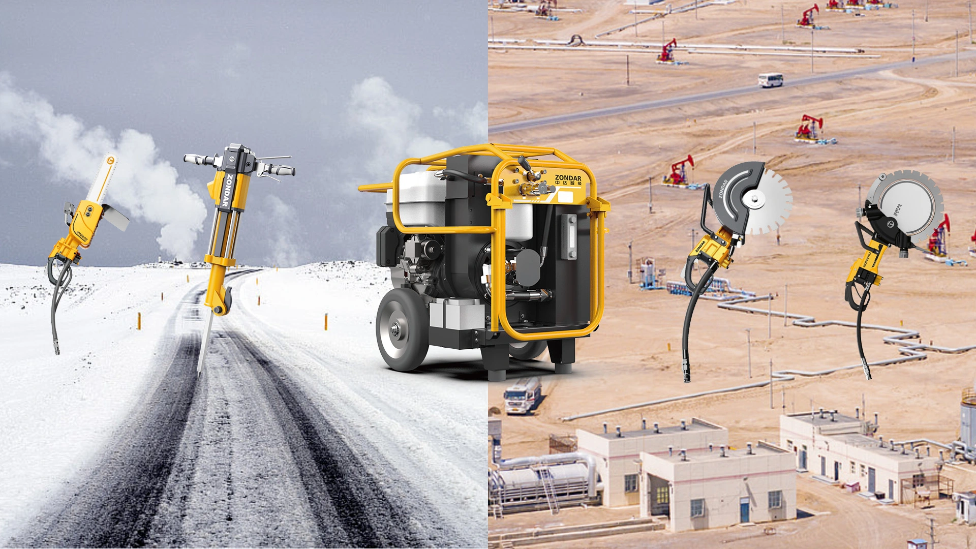
Introduction: A Road Repair Crew Working Far from the Nearest Power Supply
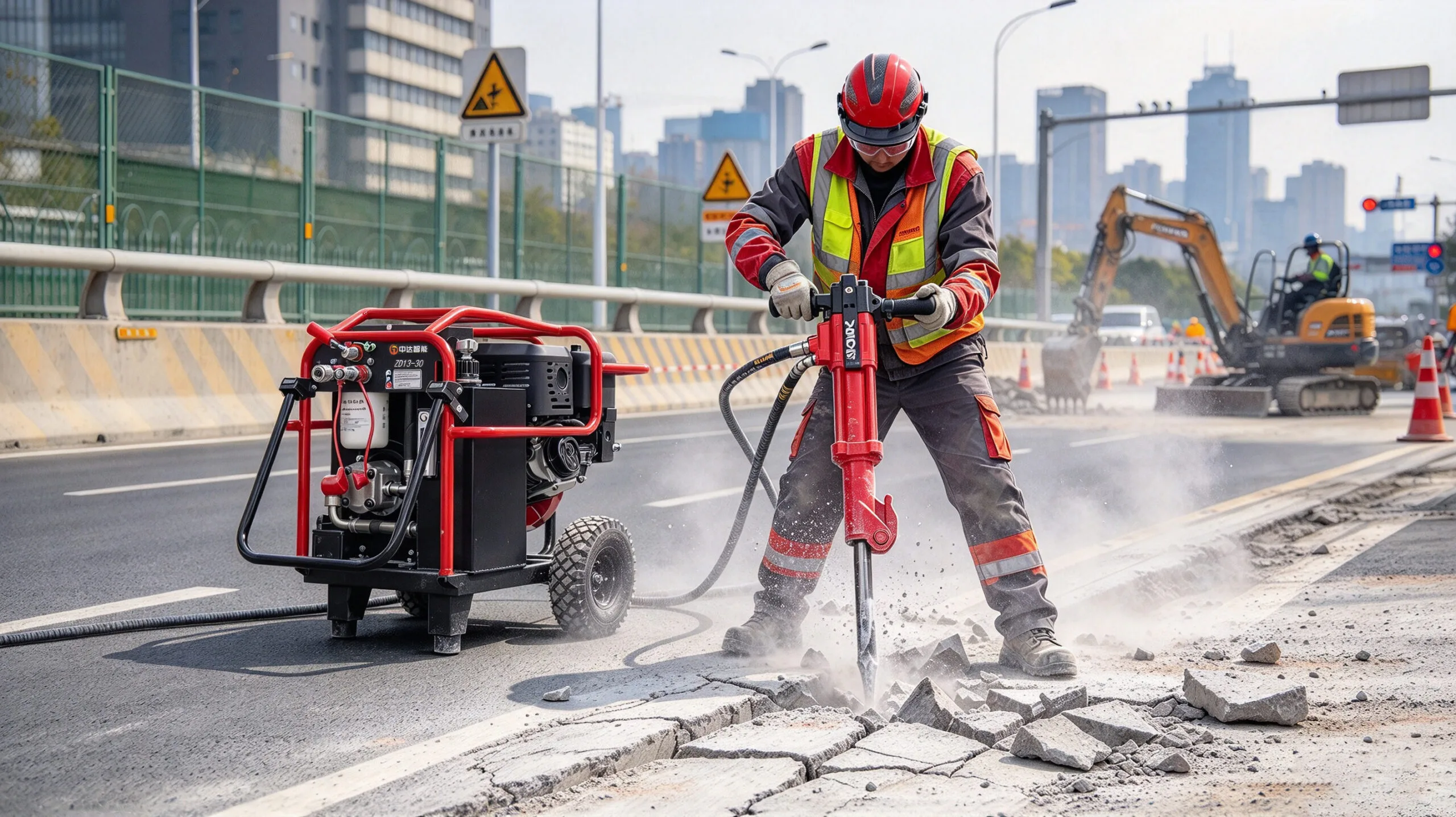
Imagine a road maintenance crew arriving at a damaged mountain road after heavy rainfall. Part of the concrete road edge has broken away, leaving cracked reinforced concrete that must be removed before the repair team can rebuild the section. The crew also needs to drill holes for anchoring, cut selected sections of concrete to create clean repair boundaries, and transport all its equipment along a narrow access road.
There is no convenient fixed power supply at the work area, and bringing a large construction machine to the site would be difficult. The crew therefore needs a portable hydraulic tool system that can be transported by vehicle and operated directly at the worksite.
For this example, the team prepares a ZONDAR ZD18-40Twin hydraulic power unit with three compatible handheld tools: a ZDHB-20 hydraulic breaker, a ZDRB-20 hydraulic rock drill, and a hydraulic ring saw such as the ZDRS-40. Each tool performs a different task, while the power unit provides the hydraulic energy needed to operate them.
The objective is not simply to bring several machines to the site. It is to organize the equipment so the crew can move from concrete removal to drilling and cutting without carrying a separate engine-powered unit for every tool.
This article walks through the preparation process, using ZONDAR equipments specifications and a representative road repair scenario. Actual tool selection and operating procedures should always be confirmed against the relevant equipment manuals and site conditions.
1. Start with the Work Sequence, Not the Equipment List
Before selecting the hydraulic equipment, the site supervisor identifies the tasks that must be completed.
First, the crew needs to remove loose and damaged concrete around the repair area. Second, it must drill holes in the sound concrete where the repair design calls for anchors. Third, some sections may need controlled cutting to establish a defined edge before the new concrete is installed.
These tasks require different tools. A handheld hydraulic breaker is suitable for breaking and chiseling concrete; a hydraulic rock drill can drill into concrete, rock, brick, or asphalt; and a suitable hydraulic ring saw can be considered where controlled cutting of reinforced concrete is required.
The crew should also assess the site before loading the vehicle. How far is the equipment from the repair area? Can the power unit be placed on stable ground? Is there enough room to route hoses without crossing vehicle paths or creating trip hazards? Will rain, mud, dust, or falling debris affect equipment placement?
These practical questions determine how the system should be transported and laid out. A tool package that matches the work technically can still cause delays if the crew cannot safely position the power unit or move between work areas.
For this example, the team plans to use one compatible hydraulic power unit and change tools as the work progresses. The tools will not automatically operate simultaneously simply because the power unit has multiple circuits; simultaneous operation must be supported by the selected output configuration and the flow requirements of both tools.
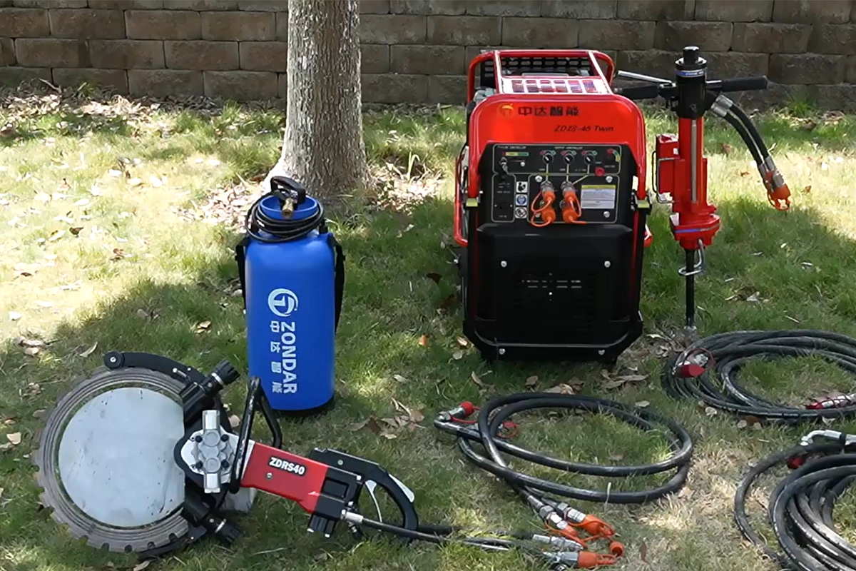
2. Select a Power Unit That Matches the Tools
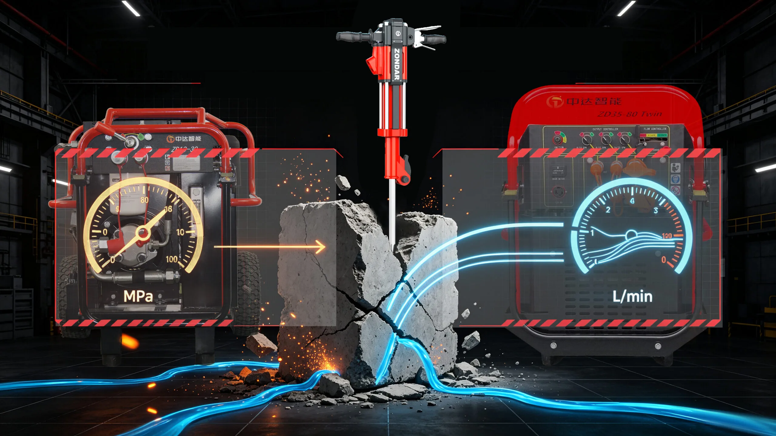
The main power source for this example is the ZONDAR ZD18-40Twin hydraulic power unit. Its pecifications include an 18HP engine, a maximum pressure of 18 MPa, and selectable flow configurations of 2 × 20 L/min, 1 × 30 L/min, or 1 × 40 L/min. It also uses flat quick couplings and a dual-circuit hydraulic design.
These specifications make it a practical candidate for a mobile job that requires several compatible handheld tools. The important point, however, is that the crew must match the selected output to the tool being used rather than treating the maximum flow figure as a universal setting.
For example, ZONDAR ZDHB-20 hydraulic breaker with an operating flow range of 20–30 L/min and a maximum pressure of 18 MPa. The ZDRB-20 hydraulic rock drill is at 20–30 L/min and a maximum pressure of 18 MPa. The ZDRS-40 ring saw is in the handheld-tool selection guide with a flow range of 20–40 L/min and an operating pressure of 18 MPa.
These ranges overlap, but they are not identical. The supervisor should check the manual for the exact tool configuration and select an approved output setting before work begins. To avoid work interuption, crew should carry out a test run before arrangement.
For a more detailed explanation of matching output flow, operating pressure, and tool requirements, see ZONDAR’s guide to hydraulic power unit selection.
The key decision is not to buy the largest available power unit automatically. It is to select a unit that meets the needs of the actual tools, the planned work sequence, and any requirement for simultaneous operation.
3. Assign the Right Tool to Each Task
Once the power unit has been selected, the crew can organize the tools according to the repair sequence.
Task A: Remove Damaged Concrete with the ZDHB-20 Hydraulic Breaker
The first operation is removing loose and damaged concrete around the repair boundary. The ZONDAR ZDHB-20 is a handheld hydraulic breaker weighing approximately 21 kg. Its operating flow range is 20–30 L/min, and its maximum pressure is 18 MPa. It uses a quick-coupling hose connection and is designed for breaking and chiseling reinforced concrete, rock, and brick.
The operator first checks the damaged section and identifies the area that needs to be removed. Breaking should follow the repair plan rather than extend unnecessarily into sound concrete. The tool should be operated using the correct working position and procedures specified by its manufacturer.
Before the breaker is connected, the crew confirms that the power unit is configured for the required flow range. The hoses and couplers are inspected for damage and contamination, and the connections are made according to the equipment manual.
The breaker is then used to remove the damaged material. If impact performance is weak, the operator should not immediately assume the breaker itself has failed. The crew should check the selected power-unit output, coupler engagement, hose condition, oil temperature, and other permitted checks before considering internal tool faults.
See the ZONDAR ZDHB-20 handheld hydraulic breaker for the published tool specifications.
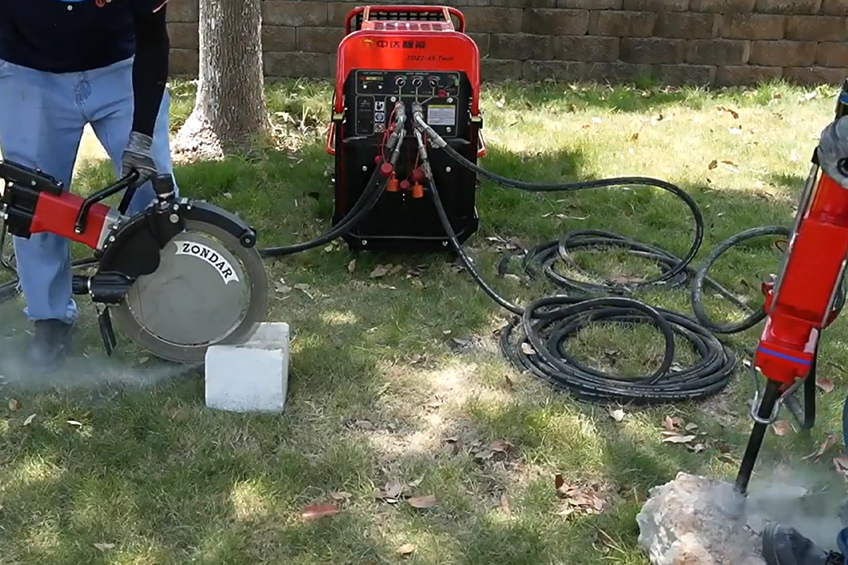
Task B: Drill Anchor Holes with the ZDRB-20 Hydraulic Rock Drill
After the damaged concrete has been removed and the repair area is ready, the crew may need to drill holes for anchors or other elements specified by the repair design.
The ZONDAR ZDRB-20 hydraulic rock drill is approximately 22 kg, with an operating flow range of 20–30 L/min and a maximum pressure of 18 MPa. The product information is with maximum drilling depth of up to 4 m and a maximum drilling dimension of 55 mm, depending on the applicable configuration and operating conditions. The tool uses quick couplings.
The crew disconnects the breaker only after the hydraulic system has been safely shut down and depressurized according to the manufacturer’s instructions. It then connects the rock drill, verifies the tool’s required operating configuration, and checks that the hose connections are secure.
The drilling pattern, hole diameter, and depth must follow the repair design. The published maximum drilling depth should not be interpreted as a guaranteed depth for every concrete type or jobsite condition.
Using the same power unit for the breaker and drill can reduce the number of separate engine-powered machines the crew needs to transport. However, it does not eliminate the need to check the flow requirements and condition of each tool whenever the crew changes equipment.
The ZDRB-20 specifications are available on the ZONDAR hydraulic rock drill product page.
Task C: Cut Concrete Where a Defined Edge Is Required
Some repair jobs require a controlled cut along a concrete boundary rather than further breaking. In this scenario, the crew may use a compatible ZONDAR hydraulic ring saw, such as the ZDRS-40, if the selected blade, cutting depth, and tool configuration are suitable for the job.
ZONDAR’s hydraulic ring saw ZDRS-40 is a 20–40 L/min operating flow range and an 18 MPa operating pressure. Because this flow range differs from the ranges listed for the breaker and rock drill, the crew must check the correct power-unit setting before changing to the saw according the manual.
The operator checks the blade, guards, water or dust-control requirements where applicable, and the cutting path. Cutting should follow the site plan and the tool manual.
This task illustrates why a multi-tool system needs more than a collection of compatible-looking connections. Each tool must be matched to the power unit’s approved flow and pressure configuration, and the operating procedure must suit the material being cut.
4. Prepare Hoses and Quick Couplers Before Leaving the Depot
At a remote site, a damaged hose or contaminated coupler can delay the whole crew. Hose preparation should therefore happen before the equipment is loaded.
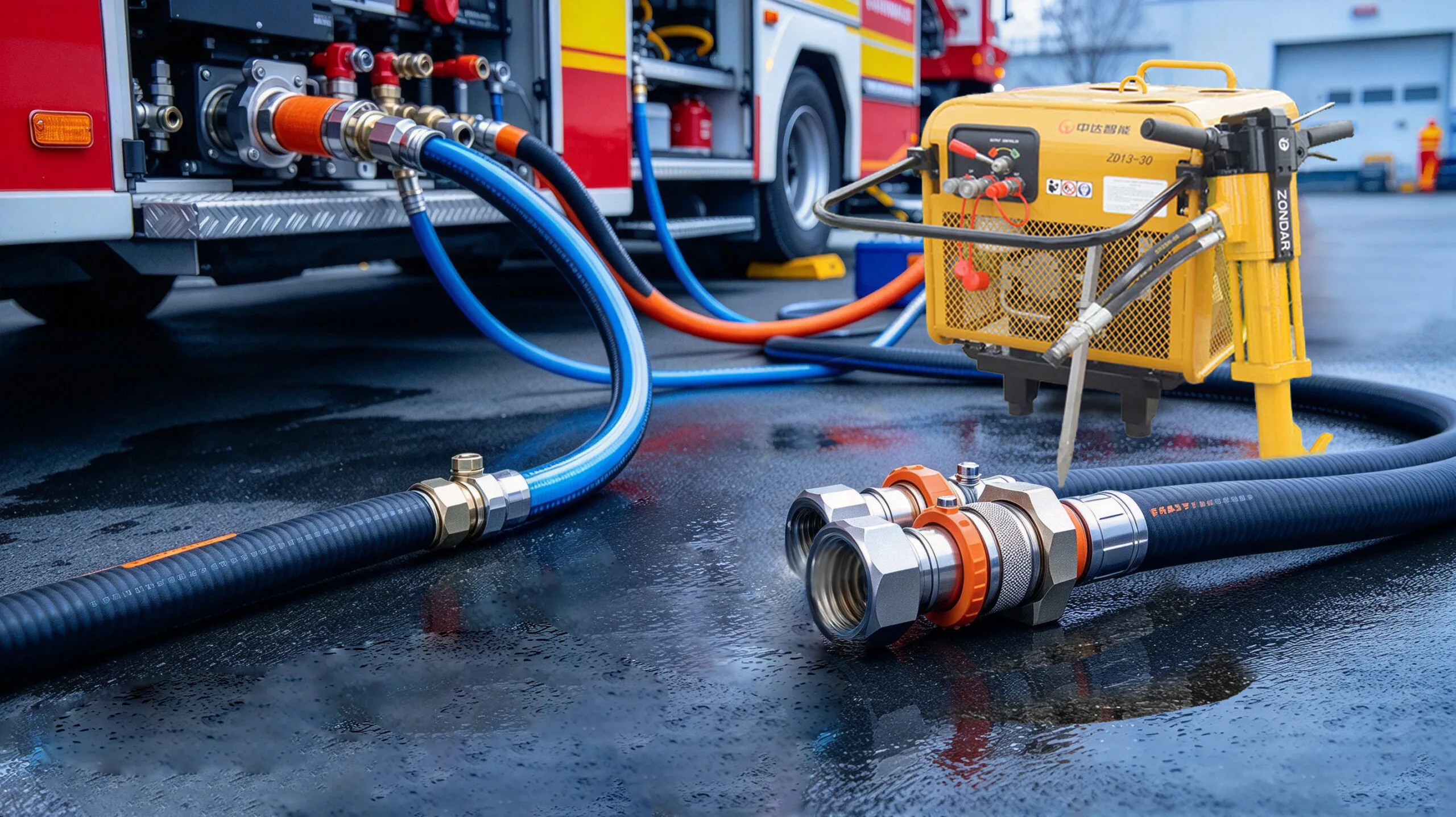
For this example, the crew prepares the hoses specified for the selected ZD18-40Twin configuration and the three tools. ZONDAR lists flat quick couplings on the power unit and quick-coupling connections on the handheld tools. The crew should confirm the exact coupling type, hose rating, and connection arrangement for its equipment rather than assume that all hydraulic hoses are interchangeable.
Each hose is inspected for cuts, abrasion, bulges, leaks, damaged fittings, or signs of crushing. Coupler faces are kept clean and protected during transport. Any hose or fitting that fails inspection should be replaced with an approved component instead of being temporarily improvised in the field.
The crew also plans the hose route and the length. Hoses should not be stretched across sharp concrete edges, trapped beneath vehicles, or placed where workers are likely to trip. If the work area changes, the hose layout should be checked again before the tool is restarted.
For more practical guidance on identifying hose and connection problems, see how hydraulic hose size affects flow and tool performance.
5. Arrange the Worksite for Tool Changes
The power unit should be positioned on stable ground in a location that allows the operator to access its controls and the crew to manage hoses safely. The location must also meet the engine’s ventilation, exhaust, heat-clearance, and refueling requirements. A gasoline or diesel power unit must not be operated in an enclosed or inadequately ventilated area.
The crew keeps the tools, hoses, and accessories organized so the next tool can be prepared without placing equipment in vehicle paths or on unstable debris. The operator should have a clear working area, while other workers remain outside the tool’s immediate operating zone.
A simple tool-change sequence helps reduce mistakes:
- Stop the tool and shut down or isolate the hydraulic power source as specified in the manual.
- Relieve residual hydraulic pressure using the approved procedure.
- Disconnect and protect the couplers.
- Inspect the next tool, hose, and connection points.
- Connect the new tool and verify the required flow and pressure configuration.
- Restart and perform the prescribed checks before returning to work.
The exact sequence must follow the equipment manufacturer’s instructions. Quick couplings make tool changes more convenient, but they do not remove the need for safe isolation and pressure relief.
If two tools are intended to run at the same time, the supervisor must confirm that the power unit’s selected circuit arrangement and available flow support both tools. In this example, sequential use is the baseline plan; simultaneous operation is not assumed.
6. Pack Fuel, Maintenance Supplies, and Essential Spares
Remote work often becomes inefficient when the crew has the main equipment but lacks simple consumables or replacement parts.
Before departure, the supervisor checks the power unit’s fuel requirements and expected work duration, while allowing for the fact that actual fuel consumption varies with engine load and operating conditions. Fuel must be transported and stored in accordance with applicable safety rules.
The maintenance kit should contain the items specified in the manuals, such as approved hydraulic fluid where required, cleaning materials for couplers, and basic tools for routine inspection. The crew should also carry suitable personal protective equipment and any task-specific accessories required for breaking, drilling, or cutting.
Spare parts should be selected according to the equipment configuration and the likely consequences of a failure. Common examples may include approved hose seals or replacement hoses, but the crew should not replace hydraulic components with parts that have not been confirmed as suitable.
The team records any pre-existing damage and checks the power unit and tools before loading. This gives the crew a baseline for identifying new problems during the job.
7. Use a Pre-Operation Checklist at the Site
Before starting the first task, the supervisor and operator conduct a short inspection. The checklist should be based on the equipment manuals and the site’s risk assessment.
Confirm that the power unit is stable, the engine and hydraulic system are ready for operation, and all guards and safety features are in place. Check the hoses, couplers, tool body, handles, and working attachments for visible damage. Confirm that the selected output setting matches the tool being used and that all connections are properly engaged.
The operator should also verify that the working area is clear of people who could be struck by debris or exposed to the tool’s moving parts. Appropriate eye, hearing, hand, foot, and other task-specific protection should be used. Concrete breaking, drilling, and cutting may create flying fragments, noise, dust, and other hazards that require additional controls.
During operation, monitor the equipment for abnormal noise, leakage, unusual vibration, loss of performance, or excessive heat. Stop work if a fault or unsafe condition is suspected. Never use hands to search for a hydraulic leak; pressurized fluid can penetrate skin and cause a serious injury.
A pre-operation check does not guarantee that equipment will never fail. It helps identify visible problems before they become a safety incident or a costly interruption.
8. Troubleshoot Performance Problems Before Replacing a Tool
Suppose the breaker begins to lose impact after the crew has worked for some time. Replacing the breaker immediately may not solve the problem.
The crew should stop work and follow the manufacturer’s troubleshooting procedure. First, confirm that the power unit is using the correct output configuration for the breaker. Next, inspect the hose and quick couplers for damage, incomplete connection, or obvious restriction. Check for visible leaks and confirm that the hydraulic oil level and temperature remain within the permitted limits.
If the basic checks do not identify the cause, the equipment should be inspected by a qualified technician in accordance with the manual. Internal faults, worn components, or problems in the hydraulic circuit may require specialist diagnosis. Operators should not loosen pressurized connections or attempt repairs on a running system.
The same approach applies if the rock drill runs slowly or the ring saw fails to perform as expected. Start with the selected configuration and visible connection issues, then proceed to more detailed checks within the limits of the operator’s training.
For a deeper fault-finding sequence, refer to ZONDAR’s article on hydraulic breaker low impact and troubleshooting, where available on the site.
9. Close the Job by Inspecting and Storing the Equipment
When the concrete repair preparation is complete, the crew shuts down the equipment and follows the manual’s procedures for relieving pressure and disconnecting tools. The hoses and couplers are cleaned and protected against dirt entering the hydraulic circuit.
The operator checks for new hose abrasion, loose fittings, visible leaks, or damage to the tool attachments. Any abnormal performance or maintenance issue observed during the work is recorded so that it can be addressed before the next deployment.
The equipment is then secured for transport. Hoses should be arranged without tight kinks, tools should be protected from impact, and the power unit should be transported according to its handling instructions.
Before the next job, the crew should carry out the scheduled maintenance required by each manual rather than waiting for a fault to appear. For additional guidance, see ZONDAR’s hydraulic tool maintenance guide.
Conclusion: A Portable System Is a Workflow, Not Just a Power Unit
Preparing hydraulic equipment for a remote road repair job involves more than choosing a power unit with a suitable engine rating. The crew must define the work sequence, match each tool to the correct hydraulic output, prepare compatible hoses and couplers, plan safe equipment placement, and carry out checks before, during, and after operation.
In this representative scenario, the ZONDAR ZD18-40Twin—with its 18HP engine, maximum pressure of 18 MPa, and selectable flow configurations—serves as the common power source for a ZDHB-20 hydraulic breaker, a ZDRB-20 hydraulic rock drill, and a compatible ZDRS-40 hydraulic ring saw. Each tool is used for a specific task, and the power-unit configuration is checked whenever the crew changes tools.
The practical advantage of a portable hydraulic tool system is that a crew can bring several task-specific tools to a remote work area without necessarily transporting a separate power source for every tool. The system works best when the equipment is correctly matched, the tool-change process is planned, and the crew follows the relevant operating and safety instructions.
For contractors and maintenance teams, preparation is what turns portable hydraulic equipment into a workable field system.